Fiber Optic Transmission Loss
What are the main sources of Optical Fiber transmission loss ?
Table of content
Contaminations
One of the largest factors in the loss of reliability
is the contamination of optical connectors end face.
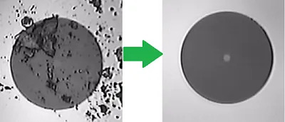
Indeed, if there is dirt, dust, oil, and other debris on the core of the fiber, the light carrying the signal won't be able to pass through the connector. Therefore, the signal's bandwidths will be reduced, or worst won't be even transmitting at all!
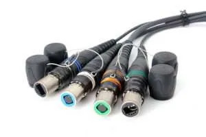
To avoid such issues, there is multiple solution. Firstly, purchase a fiber cable in line with your needs. If it's a simple patch cord for a fix indoor connection or do you need a robust mobile solution such as the opticalCON for outdoor events?
Nevertheless, nothing is 100% effective. So once in a while, even with the best material, you'll need to clean the ferrules.
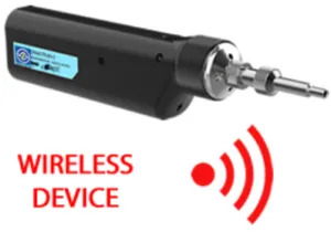
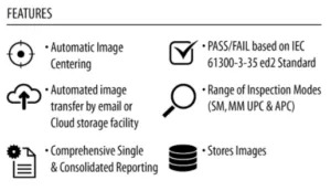
In order to do so, you can first inspect the ferrule condition, by using for example our Senko Smart Probe 2.
The last step would be to clean the ferrules using a dedicated fiber optic cleaner, removing the contamination and allowing the transmission of the signal as it should be.
Here are examples of tools that you can use to clean your fiber:
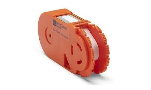
Senko Cassette Cleaner
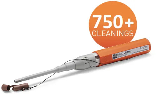
Senko SmartCleaner 1.25mm
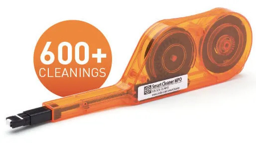
Senko MPO Plus Smart Cleaner

Senko Smart mini-Cleaner 2mm (Lemo 3K.93C)
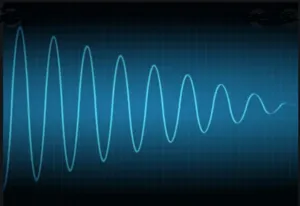
Attenuation
By definition, the attenuation is the decrease in signal strength along a fiber optic waveguide caused by absorption and scattering (which is expressed in dB/km). There are mainly two sources of attenuation.
The absorption, the portion of optical attenuation in optical fiber resulting from the conversion of optical power to heat; caused by impurities in the fiber such as hydroxyl ions.
The scattering, the change of direction of light rays or photons after striking small particles. In addition, it may also be regarded as the diffusion of a light beam caused by imperfections of the transmitting material.
To sum up, on average, the attenuation per wavelength is the following:
- @850nm: 3.5dB/km
- @1300nm: 1.5dB/km
- @1310nm: 0.7dB/km
- @1550nm: 0.5dB/km
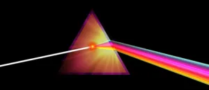
Dispersion
The optical fiber dispersion describes the process of how an input signal broadens/spreads out as it propagates/travels down the fiber.
The modal dispersion is caused by the time difference between the fastest and the slowest mode of light entering the fiber at the same time and travelling a kilometre (max 1 to 3 nanoseconds).
The spectral dispersion depends only on the source, if we use a LED, which as 20 times more spectre compared to a laser, the spectral dispersion won't be eliminated.
Bending
The bending is attenuation caused by high-order modes radiating from the outside of a fiber optic waveguide which occur when the fiber is bent around a small radius.
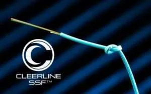
Indeed, even the amazing Cleerline SSF Fiber technology has losses due to bending. Consequently, even with Cleerline SSF Fiber, you must untight your knot to make your fiber work properly.
Macrobending (major/visual angle) will cause light to leak out of the fiber, causing signal attenuation.(Minimum bending radius of a cable).
Microbending (small variations/bumps in the core to cladding interface) can cause high-order modes to reflect at angles that will not allow further reflection.
On average, the minimum radius curve equal to 20-30 times the diameter of the external cable.
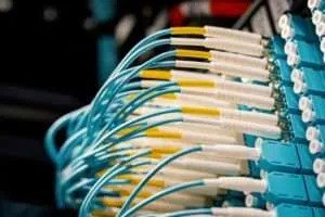
Connections
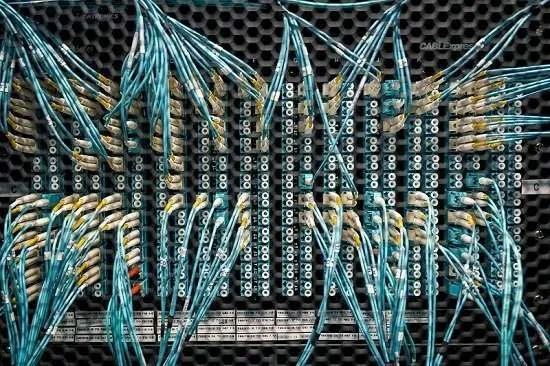
Each connection is a source of loss caused by the connectors (spliced or not), the back reflection, the optical return loss,... Therefore, when you have a full network, you have to take into account all the possible losses that you have per connections.
A connector can cause losses due to misalignment, core not perfectly centred in the cladding, or cladding diameter mismatch,...
A spliced connector adds an extra loss due to the reparation (whether it is a mechanical or fusion splice).
Each connection is a source for back reflection, the amount of light reflected back from an optical component of a transmission link.
The back reflection = 10Log(Pr/Pi) where Pr = Reflected Power and Pi = Incident Power.
So the smaller is the value, for the back reflection, the better it is!
Each connection is also a source for optical return loss (ORL) which represent the total accumulated light reflected back to the source along the link due to: connectors back reflexion, diffusion, Rayleigh back scattering,...
The ORL = 10Log(Pt/Pr) where Pt = Transmitted Power at the fiber origin and Pr = Received Power.
So the bigger is the value, the better!
In conclusion, as a rule of thumbs, to compute all the losses across a transmission, we use the following values:
- Connector = 0.4dB
- Splice MM = 0.2dB
- Splice SM = 0.1dB
- SM Fiber - 1550nm = 0.5dB/km
- SM Fiber - 1310nm = 0.7dB/km
- MM Fiber - 1300nm = 1.5dB/km
- MM Fiber - 850nm = 3.5dB/km